Most common microelectronic filter components
Most common microelectronic filter components
The main purpose of Electrical filter components (EFC) is to reduce the electromagnetic disturbances in a microelectronic system from the external environment. In [1], these techniques are called “Devices Used to Suppress Transients”.
Electromagnetic disturbances can be provided from different sources, such as:
- Electromagnetic interference (EMI);
- Radio frequency interference (RFI);
- Electrostatic discharge (ESD);
- Other electronic components.
The EFC are essential to reduce the input electrical noise on a PCB board and increase the system life cycle, avoiding damage to included components. This article is an introduction to EMI, RFI, and ESD filter components which are important to design electrical circuits. The incorporation of protection circuits makes a microelectronic system more reliable and protected.
Decoupling & Bulk Capacitors
Microelectronic components are designed to have a stable power supply. It has been observed bad circuitry behavior related with lack of power quality signal [1]. Field equipment, which is powered through external DC voltage, can have noisy voltage ripples. This problem has a bigger impact on industrial systems, where exist high electrical currents and consequently higher electromagnetic noise.
To reduce noise in DC power and protect the PCB components, decoupling capacitors (also called bypass capacitors) are used. The decoupling capacitors theoretical principle is to oppose any unexpected change in the input voltages, absorbing noise and making the desired DC voltage as smooth as possible. Two major electrical functions are performed:
- If the input voltage drops a decoupling capacitor will be able to provide energy to an integrated circuit (IC) to keep the voltage stable;
- If the voltage increases a decoupling capacitor will be able to absorb the excess energy and keep the voltage stable.
The following image presents a typical application.
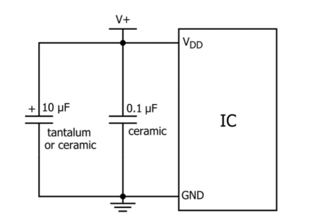
Decoupling capacitors are placed in the power input lines, close to the integrated circuit between the power source and the ground. An  –
–  capacitor helps to smooth out any low-frequency changes in an input voltage. Usually, tantalum capacitors are used to lower frequencies. An
  –
–  capacitor help to smooth out high-frequency noise in the circuit, being recommended to use ceramic capacitors. Ceramic capacitors have better high-frequency characteristics compared with other capacitors, like aluminum electrolytic capacitors ([1]).
Bulk capacitors have a large capacitance, preventing amperage from dropping too low when the power supply is unavailable. The capacitors are used in parallel, like decoupling capacitors [3].
Usually, the datasheet of the integrated circuits indicates which capacitors are more advisable to use with.
Differential & Common Mode Choke
An Inductor is an electronic component constituted by a coil, which stores energy in the form of a magnetic field. This component permits DC Current to flow freely but resists to AC current flow through it. When dealing with changes generated by noise (EMI or RFI), they prevent noisy currents to flow into your PCB board.
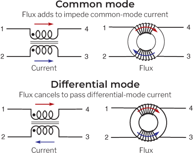
A typical inductor, for preventing noise in DC power channels, is the choke filter [ 5, 1]. The choke filter consists of two coils wound, with the same number of turns around a magnetic core, which can operate in two modes:
- In common mode, the choke increases the input impedance in the circuit for high frequencies, that is, it offers resistance to the passage of noise in common mode. The impedance increases in common mode through magnetic fields flowing in the same direction in the magnetic core, increasing the inductance.
- For signals in differential current mode, will have opposing magnetic fields, thus having a smaller attenuation, the current flow in the opposite direction, and the flux cancels.
Figure 2 complements the interpretation.
Varistor & Fuse
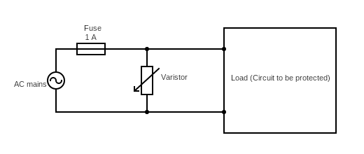
Varistor is an electronic component whose resistance is inversely proportional to the voltage in its terminals. A varistor component with high voltage there is a resistance drop, and with low voltage there is a resistance grow. This behavior allows the protection to overvoltage in short periods and can be considered a protection against Electrostatic discharge. This component is implemented in parallel, like decoupling capacitors in Figure 2 (view [1]).
It is highly recommended to protect your system when a short circuit system occurs in your board, like when a varistor is damaged. You will have a high current running inside the system in this situation. So to prevent that, you usually use a Fuse. The Fuse is a component used for overcurrent protection, being constituted by a filament that melts when a certain current threshold is crossed over a certain time. In Figure 2, you can observe a typical application with a Fuse and a Varistor [1].
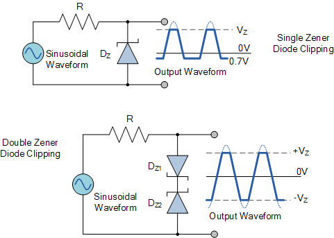
Zener Diode
The Zener diode is a semiconductor that permits the current to flow forward and reverses direction. The forward voltage is the voltage needed to get current to flow across the pn junction, just like a normal diode. The main difference with this component, is to have a low reverse breakdown voltage, well-defined, which conducts current when this reverse breakdown voltage is crossed.
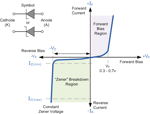
In Figure 4 it is possible to observe the Zener diode operation zones and see that, between breakdown voltage and forward voltage, the current doesn’t flow. The Zener diode is used in different applications like overvoltage protection (Figure 5).
Examples of application
With the present components, it is possible to construct different circuits to protect boards or systems, as mentioned above. Figures 6 and 7 present some examples.
Figure 6 presents the 24 VDC power supply filtering using the previously mentioned components.
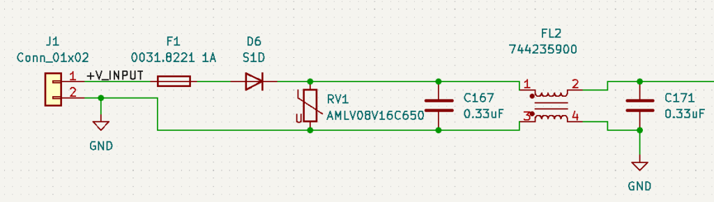
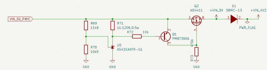
Figure 7 presents an overvoltage protection circuit to power supply above 5 VDC, used to supply a power management integrated circuit (PMIC) to a microprocessor.
[1] also describes some overvoltage protection circuits.
References
[1] Paul Scherz and Simon Monk. Practical Eletronics for Inventors, volume 4. MC Graw Hill Education, 2016.
[2] Robert Keim. Clean power for every ic, part 1: Understanding bypass capacitors. https://www.allaboutcircuits.com/technical-articles/clean-power-for-every-ic-part-1-understanding-bypass-capacitors/, 2015.
[3] Texas Instruments. Voltage margin and bulk capacitance. https://training.ti.com/ti-precision-labs-motor-drivers-voltage-margin-and-bulk-capacitance, 2022.
[4] Coilcraft. A guide to understanding common mode chokes. https://www.coilcraft.com/en-us/edu/series/a-guide-to-understanding-common-mode-chokes/, 2022.
[5] LLC Ahmed Alamin Associate Product Engineer Abracon. Common mode chokes basics and applications. https://abracon.com/uploads/resources/Common-Mode-Chokes-Basics-and-Applications.pdf, 2022.
[6] OurPCB. Metal oxide varistors(mov): A voltage surge protection device. https://www.ourpcb.com/metal-oxide-varistors.html, 2022.
[7] EletronicsTutorials. The zener diode. https://www.electronics-tutorials.ws/diode/diode_7.html, 2022