First-Principle Modelling
Introdução
Simulation based on first principles has been an essential technique while designing new equipment or
processes. It uses scientific laws from physics and chemistry to specify the relations between input and
output. Considering the digital twin objectives, first-principle techniques have been used to promote
runtime verifiability of the production processes.
The results have been demonstrated to be excellent when compared to other techniques. The disadvantage
of the first-principle technique is the inherent complexity of the models, requiring the usage of professionals
with extensive knowledge in the field and leading to the inability to consider and predict random events
of ”real-life” use.
The scientific literature has introduced methods combining first-principle theories with data mining tools,
permitting to adapt less detailed first-principle models to restrict statistical methods on the desired out-
put. Combining first-principles analysis with data mining enables the use of both approaches’ advantages.
This article will focus on an example that explains first-principle models from the scientific literature.
To improve the method explanation, the extraction of information in literature, referencing related doc-
uments, will be embedded in the example.
Dynamic separator modelling
Oncontrol desired to understand the equipment eficiency and the model’s potential use to verify dependencies of process variables on final product quality. Separators are used in closed-circuit plants, being their primary function to classify the particles as fine or coarse. Particles larger than pretended return to the mill, and those below the desired size are classified as final products, reducing over-grinding. Therefore, overall efficiency increases.
In high-efficiency separators, the fine fraction has a low quantity of coarse particles, and the coarse
fraction has a low amount of fine particles. Air separators classify material by using an airflow and a
rotor cage. The guide blades on the rotor cage direct the airflow to the centre [San90]. They are more versatile, less sensitive to variations in the feed stream, and provide greater control over the final product and the cooling and drying of the material, making it easier to produce finer products.
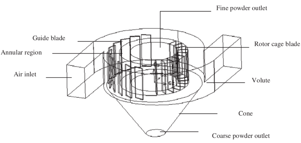
The fundamentals of air separators are feeding material onto the rotating distribution plate and material
dispersion due to centrifugal force. The air stream in the classification zone drags the smaller particles
to the fine stream, and the larger ones fall into the coarse stream.
Dynamic separators can be of one of three generations.
The first generation is the most basic, with airflow generated by a fan within the separator’s body. Some advantages are the possibility of mechanical adjustments, very large flow rates, and the flexibility to produce different qualities of particles. On the other hand, the efficiency is worse than with other generations, especially with high circulation loads, due to poor distribution of the material. Also, there is little to no possibility of cooling and drying. [Pfief]
Second-generation separators are identical to first-generation ones but use cyclones to improve fine collection efficiency, and the circulating fan lies on the exterior. The particles that exit the separator on the fines tail head to the cyclones. These apparatuses classify the ”true fines” as the final product and recollect the misclassified coarse particles. They are more efficient than first-generation systems, consume less power, and experience less wear on internal parts. Nevertheless, more space is required for the installation.
The third generation, introduced in the 1980s, uses an external fan, and fineness is controlled by adjusting the rotor speed or airflow. This is the most used form of separator in the cement industry, and some studies claim that it can reduce by-pass to 5-10% while improving production rate by 15-35%. Third-generation separators have a lower proportion of excessively fine grains than the other two. The employment of a rotor cage as the classification component and the uniform field in the classification zone created by the tangentially directed airflow is advantageous, according to [Guo07].
As stated by [Guo07], the separation process obeys the laws of physics, being the centrifugal ( ) and drag (
 ) forces given by:
(1) 
(2) 
Where:  is the particle mass,
  its volume,
  its diameter,
  its density,
  its radial velocity,
  is the drag coefficient, which depends on Reynolds number
  ,
,  is the radial velocity of the airflow,
  its tangential velocity (equal to the particle’s),
  is the air density, and
  is the coordinate in the radial direction.
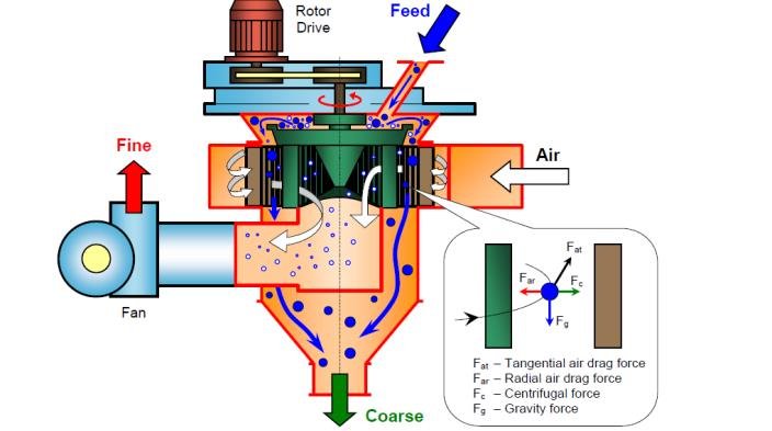
In a situation of equilibrium (correspondent to the cut size,  ), assuming that slip between particle and air tangentially velocity is nonexistent, and considering the situation where the particle has no radial velocity.
(3) 
The working parameters of the system allow for obtaining the radial and tangential components of the airflow.
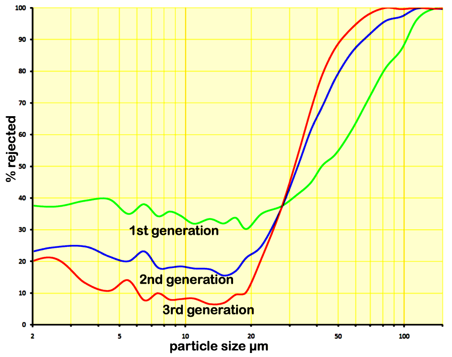
Tromp Curve
One way of assessing the efficiency of a separation process is calculating the Tromp Curve using operational data. This curve represents the fractional recovery of particles as a function of their size. Fractional recovery is the fraction of particles recovered to the coarse stream and returned to the mill. Cut size corresponds to the size which has a fractional recovery of 50% [Bel16]. The curve depends on the physical parameters of the process, affecting particle classification and the by-pass (fraction of material that ends in the coarse stream independently of its size), like the quantity and type of grinding aid, the quality of material, and air through the separator, cement type and fineness, the circulating factor, and the quality of material sampling.
It is clear from the Tromp Curve for each generation of dynamic separators (under the same conditions) that the third generation’s classification process is significantly better. The lower by-pass and higher sharpness values demonstrate the benefits of using these technologies ( Figure 3).
Conclusion
In this article, a presentation of dynamic separators and physical governance functions are provided through the article. References from where physical laws have been extracted were also presented in the article.
Referências
[San90] Isidro Contreras Sanchez, Koji Matsushita, and Francisco Carlos Pons. Moagem e Moinhos. FILK e S.A. Indústrias Votorantim, 1990.
[Gao13] Liping Gao, Yuan Yu, and Jiaxiang Liu. Study on the cut size of a turbo air classifier. Powder Technology, 237:520–528, 2013.
[Pfeif] Christian Pfeiffer Systems and components. Comparison types of separator.
[Guo07] Lijie Guo, Jiaxiang Liu, Shengzhao Liu, and Jinggang Wang. Velocity measurements and flow field characteristic analyses in a turbo air classifier. Powder Technology, 178(1):10–16, 2007.
[Bel16] T. Belhaj, M. Higazy, A. Gaafer, and B. ELMogy. Improvement of productivity using tromp curve measurement for cement separator processing technology. Scientific Journal of October 6 University, 3(2):35–44, 2016.
[Moo21] Dylan Moore. Size reduction and grinding. https://www.cementkilns.co.uk/grinding.html, 2021